Wi-Fi relay controlled by the mobile app
Assembling the device
What we used to assemble this device:
- Breadboard - 2 pcs.
- IoT platform ESP-WROOM-32 DevKit v1 - 1 pc. (or any other platform variation with or without ESP32 microcontroller on Dev Board).
- Mini-relay (Zelo-module) - 1 pc.
- Resistors (220 Ohms) - 1 pcs.
- 5 mm LED - 1 pc.
- Tactile push buttons with caps - 2 pcs.
- Connection cable set.
The scheme of the device is quite simple, you can find images instantly in a Google search. As a result, the device runs without any interruptions.
Example of the Wi-FI relay prototype:
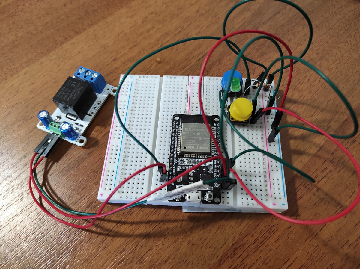
Device scheme:
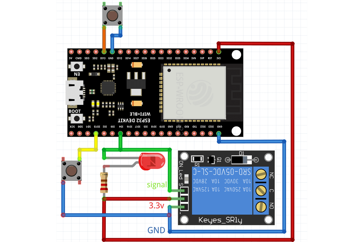
A brief description of the scheme:
- A relay is connected to the microcontroller (on the left in the picture), through which the power to the lamp will be switched on and off.
- The blue button is needed to physically switch the state of the relay. (Controlling the lamp without a smartphone.)
- The yellow button resets the device to its "factory" state.
- The green LED is needed to indicate the status of the lamp and will light up at the same time.
Registration on the IoT platform
To prepare the assembled device for operation, you need to register as a vendor on the IoT platform, 2Smart Cloud. This platform will not only help prepare the firmware for the smart relay but set up the mobile app for management and provide cloud infrastructure for further operation and support for the device.
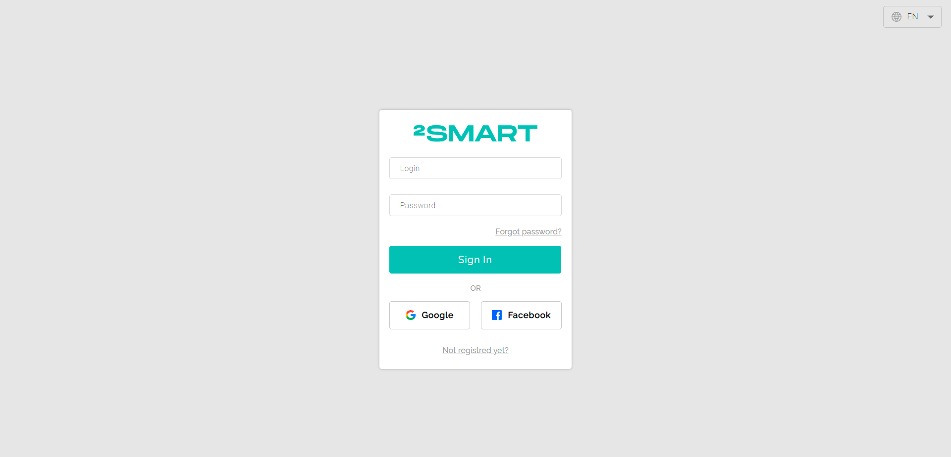
1- Go to https://cloud.2smart.com/
2 - Create a new account or sign in with your Google or Facebook account. When you sign in through a social network, you will receive an automatically generated password via email. It is possible to change the password in your dashboard. You may need the password to connect third-party services without authorization through a social network.#nbsp;The same credentials are used for authorization in the mobile application.
Creating firmware
1 - After registering, the system will offer to create a test product based on a virtual device. It is advised to do this to learn more about the possibilities of the platform.
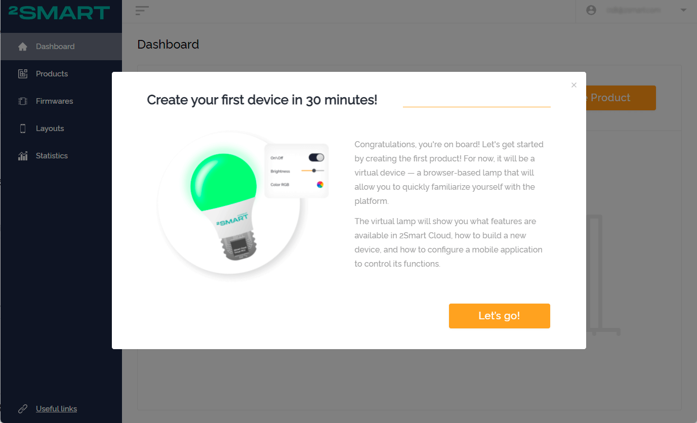
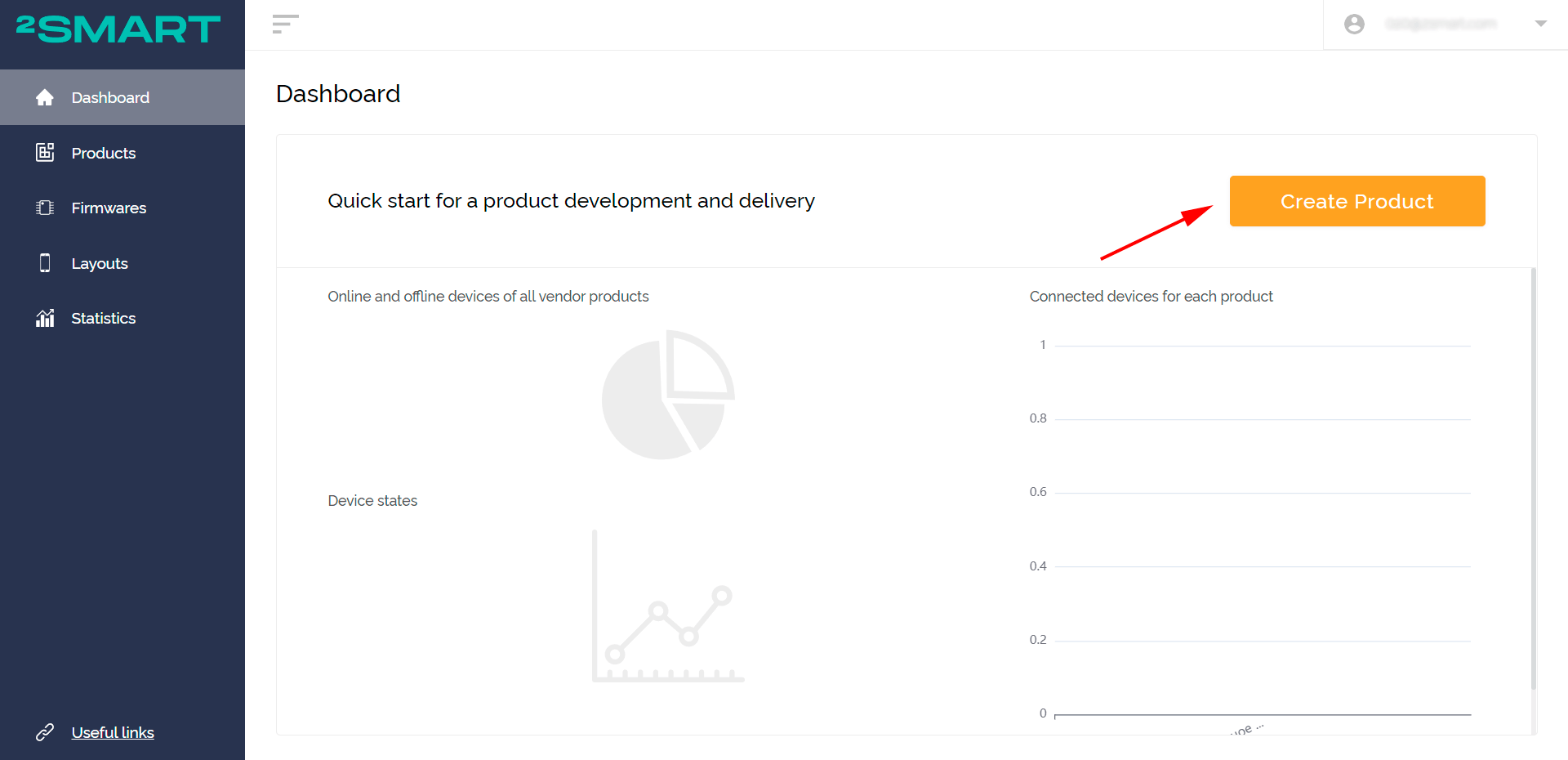
2 - After completing the tutorial, return to the main page of the vendor dashboard. Click "Create Product".
Note: The same button on the “Products” page launches the standard version of creating a product with 2Smart Cloud.
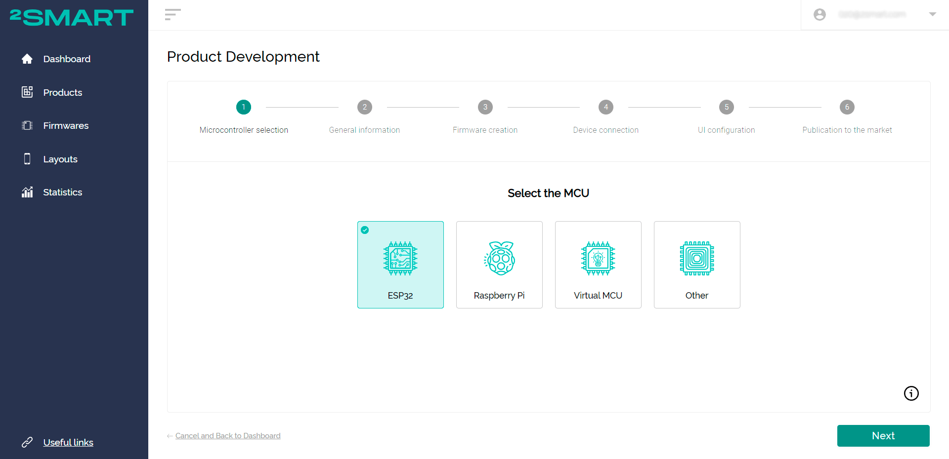
3 - Select the microcontroller that the smart device is based on. In our case, it is the#nbsp; ESP32. Click “Next”.
The platform also supports alternative MCU’s like the Raspberry Pi, as well as ready-to-use tools for them. You can use a personal solution and write compatible firmware using our documentation.
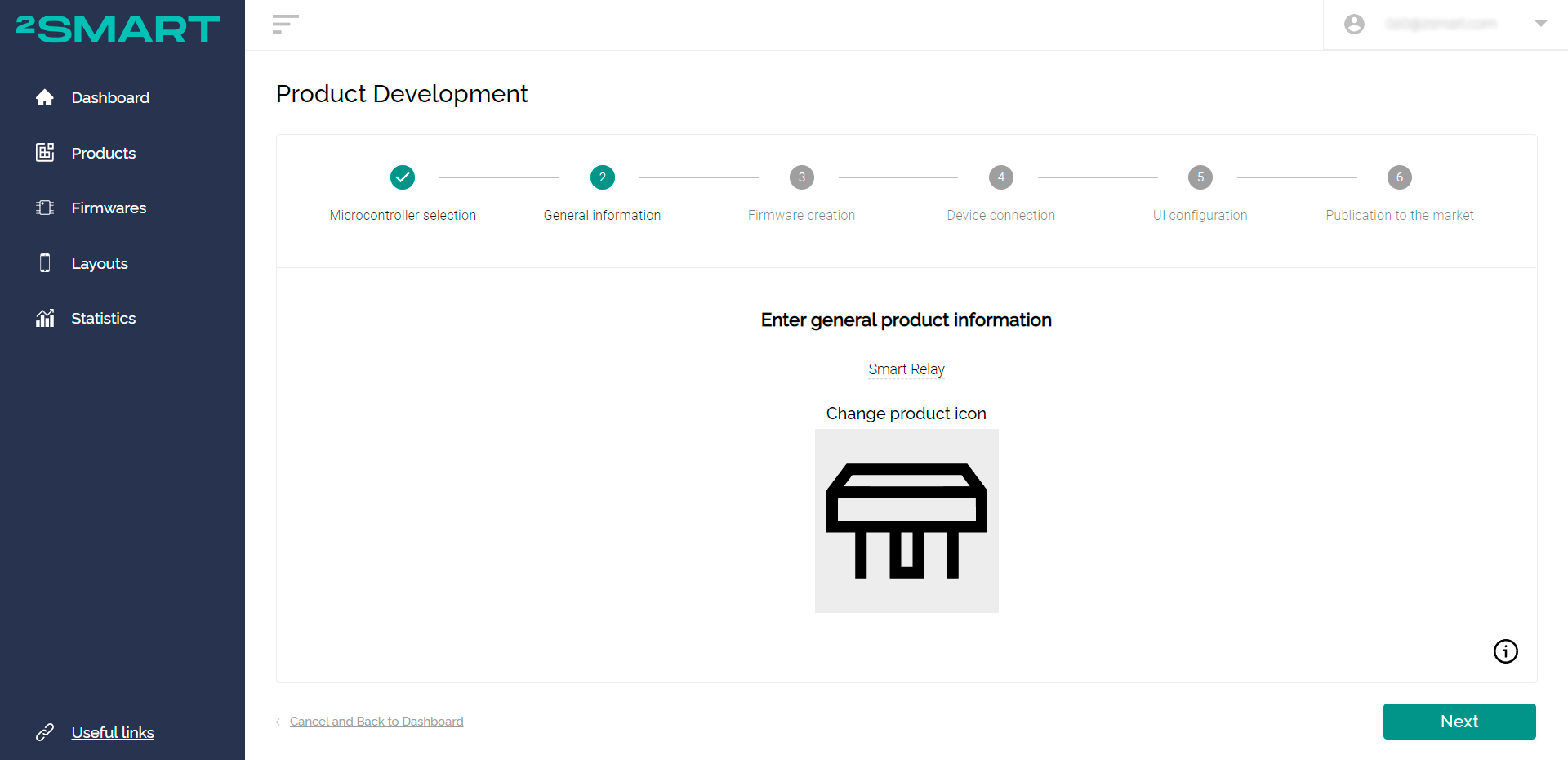
4 - Provide information about your device then enter a name and upload an icon. This information will be visible to end-users in the mobile app. Click “Next”.
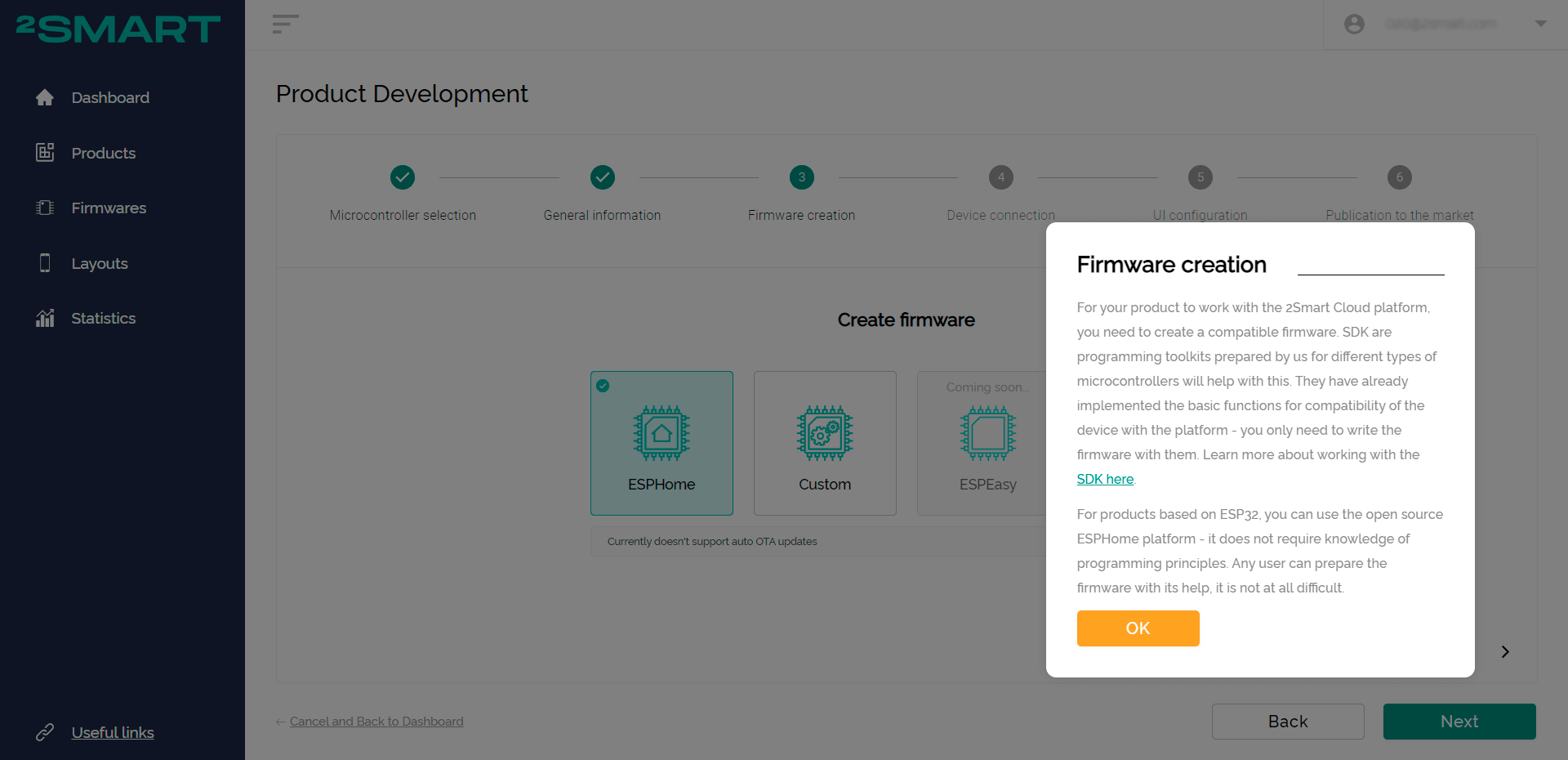
5 - Select the basic firmware. For the ESP32 microcontrollers, these are the ESPHome or Custom variants.
An advantage of using the ESPHome open-source platform is that no knowledge of programming is required when preparing firmware. It is an extremely simple set of libraries and tools which are approved by many open-source examples. Instructions can be found in the documentation of the platform.
The Custom firmware option allows you to prepare code in any language from scratch provided that you follow the principles of platform compatibility. Another custom option is your firmware which has been created based on our prepared SDK (ready-made C++ template with already implemented key functions). Details on both Custom firmware preparation options can be found in the 2Smart Cloud platform documentation.
In this tutorial, we will demonstrate how to create a device based on ESPHome firmware in a short amount of time. After selecting, click "Next".
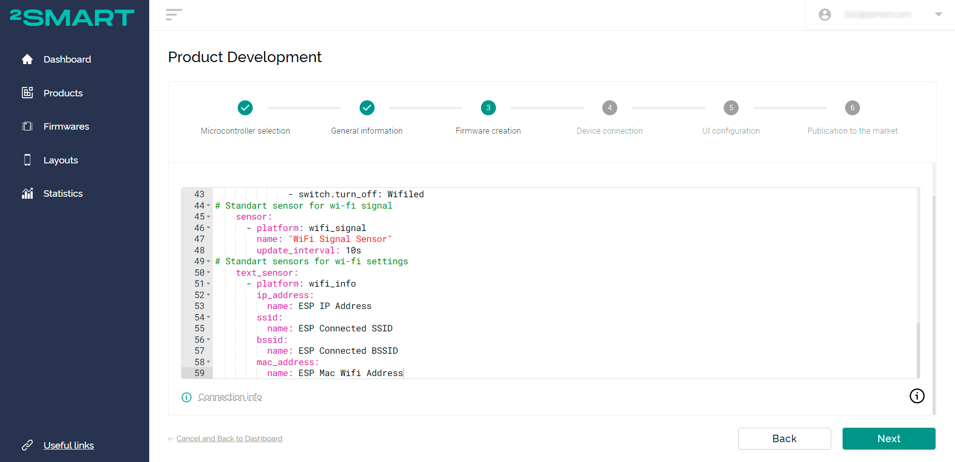
6 - After proceeding to the next step, you will get access to the code editor to configure the running of the firmware. The firmware code for the smart relay in our case are as follows:
# Switchers for relay and wi-fi led indicator
    switch:
      - platform: gpio
        id: l2
        name: relay
        pin:
          number: GPIO4
          inverted: True
      - platform: gpio
        id: Wifiled
        name: ledWifi
        pin:
          number: GPIO2
# Physical button for relay switching
    binary_sensor:
      - platform: gpio
        pin:
          number: GPIO13
          mode: INPUT_PULLUP
          inverted: True
        name: sensor_button
        on_press:
          then:
            - switch.toggle: l2
# Physical button for reset creds for production devices (only for 2Smart Cloud version of EspHome)
      - platform: reset_sensor
        pin:
          number: GPIO15
          mode: INPUT_PULLUP
          inverted: true
        name: Reset button
        filters:
          - delayed_on: 2s
    interval:
      - interval: 10s
        then:
          if:
            condition:
              wifi.connected:
            then:
              - switch.turn_on: Wifiled
            else:
              - switch.turn_off: Wifiled
# Standart sensor for wi-fi signal
    sensor:
      - platform: wifi_signal
        name: "WiFi Signal Sensor"
        update_interval: 10s
# Standart sensors for wi-fi settings
    text_sensor:
      - platform: wifi_info
        ip_address:
          name: ESP IP Address
        ssid:
          name: ESP Connected SSID
        bssid:
          name: ESP Connected BSSID
        mac_address:
          name: ESP Mac Wifi Address
Firmware code comments:
- The "Switchers for relay and wi-fi led indicator" block describes a sensor to control the LED connected to pin 2 of the ESP platform and a relay that is connected to pin 4.
- The "Physical button for relay switching” block outlines the settings of the button, which is connected to pin 13 of the ESP platform (blue in the photo). This is the button that, when pressed, forcibly switches the state of the relay.
- The "Physical button for reset creds for production devices" block describes the settings of the second button, which is connected to pin 15 of the platform (yellow in the photo). It resets the platform settings and reverts it to its factory state (Reset button).
- The "Standard sensor for Wi-Fi signal" block is needed to transmit data regarding the state of the Wi-Fi with specified regularity. (in the example code, every 10 seconds)
- The "Standard sensors for wi-fi settings" block contains the settings of specific text sensors about the state of the Wi-Fi network. This information will be visible in the application interface.
After setting the firmware code, click "Next".
7 - At first, a firmware of testing device was built on the 2Smart Cloud platform. One has to connect to the test environment and debug the prototype device to check the functionality and control methods.
To start building the firmware of testing device, click "Build firmware" on the new screen.

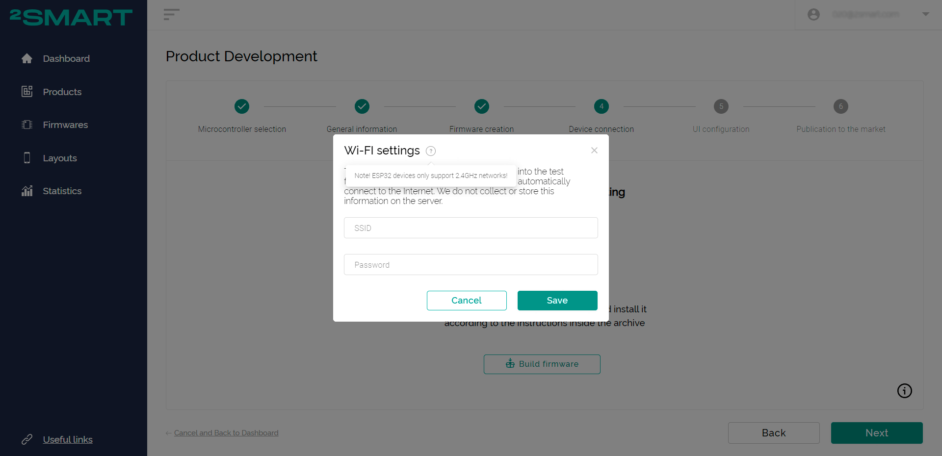
8 - Set the parameters of your Wi-Fi network and click "Save". Access to your home or work network is necessary for the device to go online after downloading the test firmware and connecting to the platform.
9 - Wait until the test firmware is built.
The firmware which is ready for uploading to the device is built directly on the platform server. There is no need to install the firmware on your computer. After a simple firmware act, the device will connect itself to the selected Wi-Fi network and then to the platform.
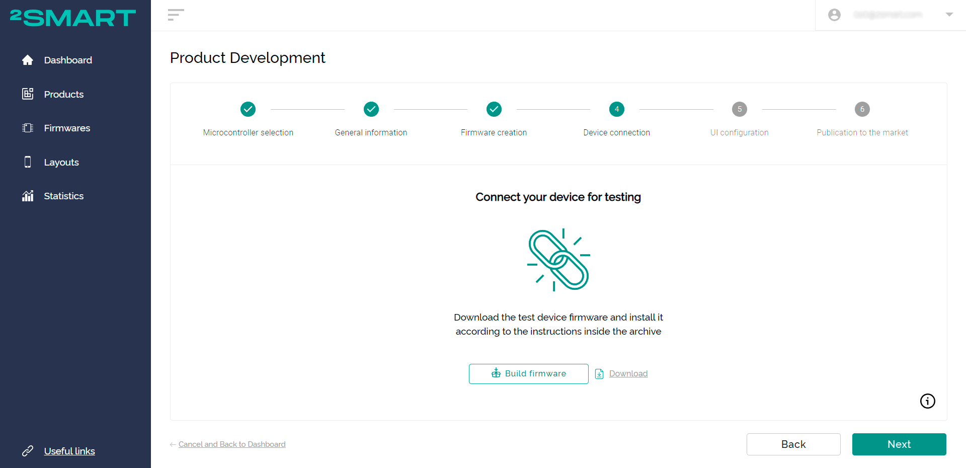
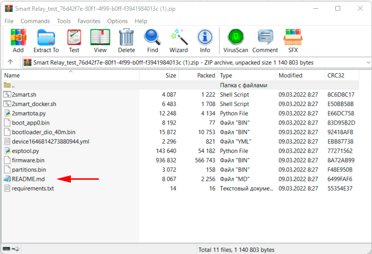
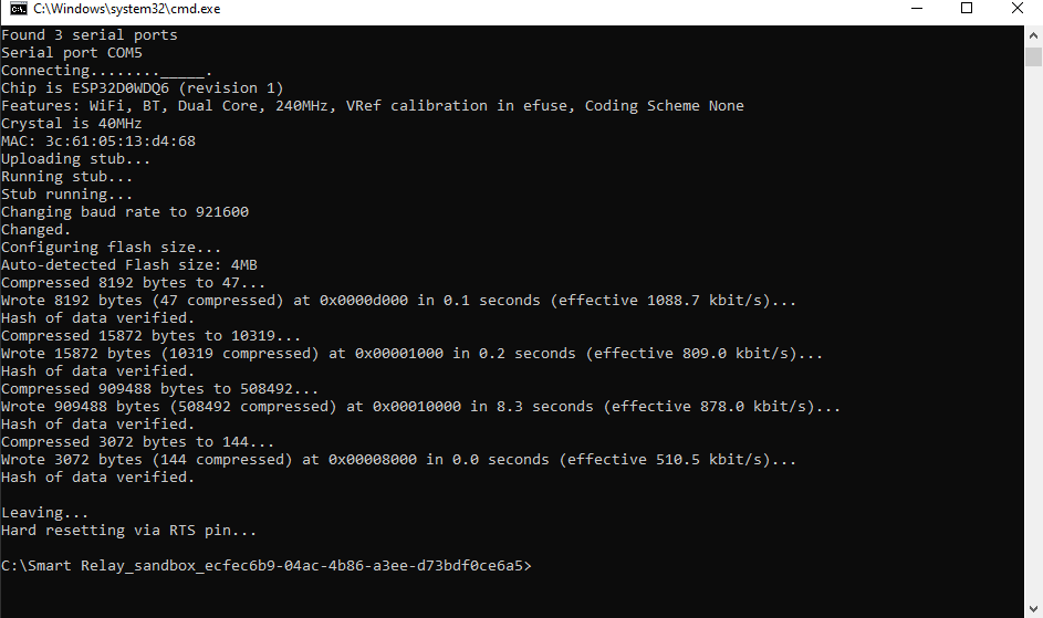
10 - Download the firmware. Within the archive, there will be a ‘readme.md’ file describing the process of the firmware installation. Install the firmware on the device following the instructions. (Use the USB cable to connect the device to your computer.)
Firmware is available for Mac OS, Linux and Windows.
Attention! If the firmware is already written to the microcontroller, remove it by following the instructions in the ‘readme.md’ file or as described in the documentation.
11 - After successfully installing the firmware, return to the 2Smart Cloud platform and click "Next". You will receive a notification that your device is detected. In some cases, you might have to disconnect the ready-to-use IoT device from the power and connect it again to detect the device.
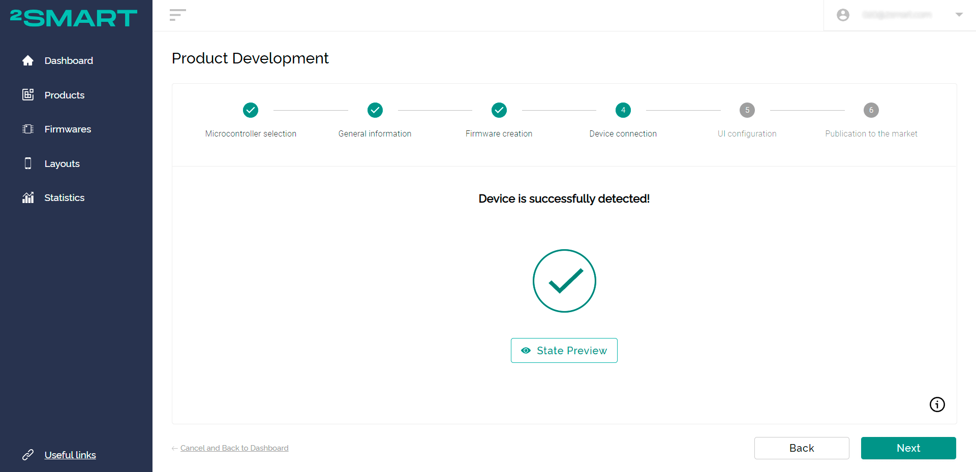
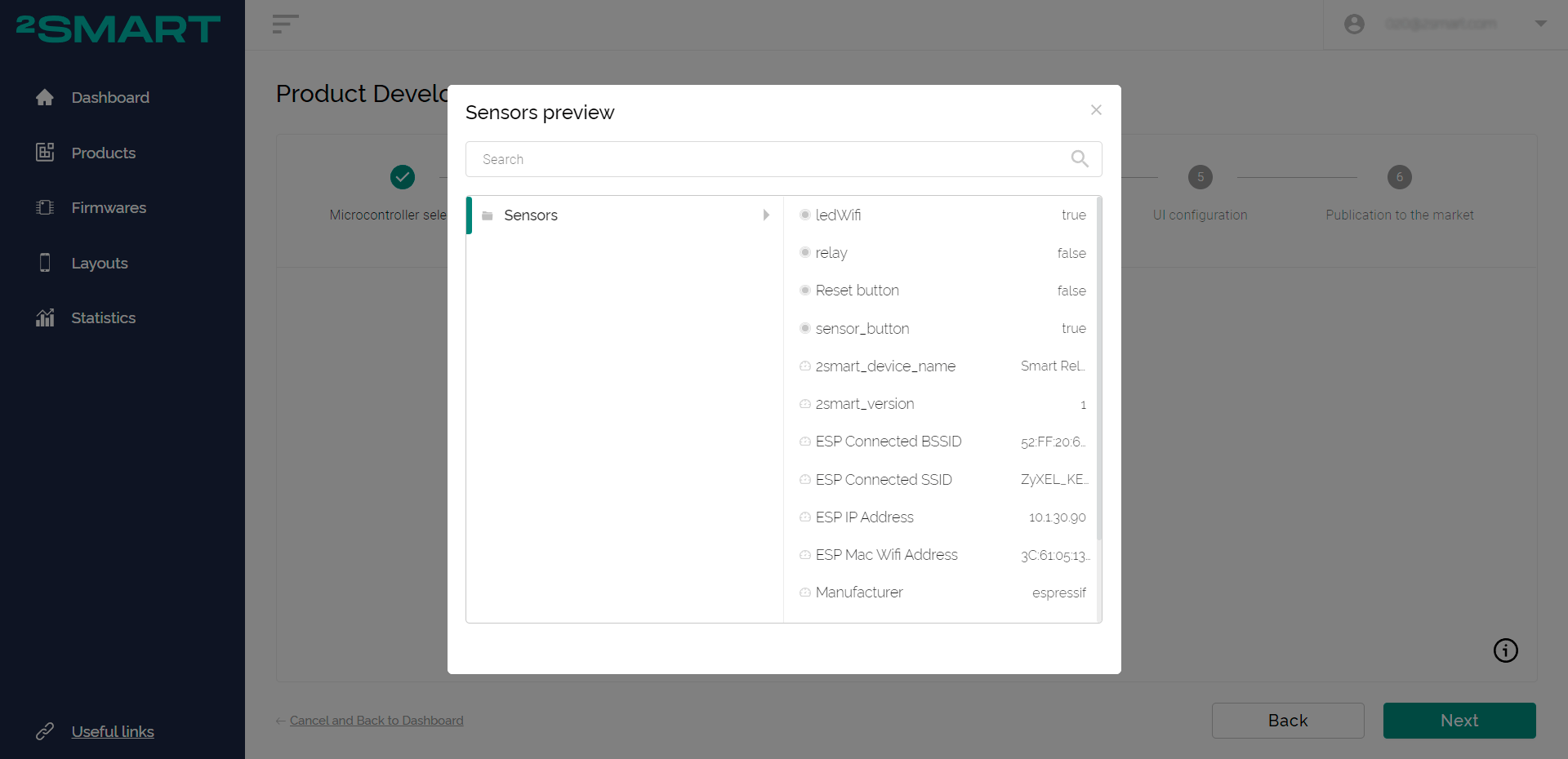
12 - Click the "Preview State" link to see the data of your device’s sensors. Note that at this stage you already get real data from your prototype which shows the current state of the sensors. It is updated in real-time.
Configuring the interface of the mobile application
After the system detects the device with the test firmware, you can configure the interface of the mobile application to control the device from a smartphone.
1 - Tap "Next" on the screen which notifies you that the device was successfully detected. The mobile app setup screen should then open.
The application interface is then created automatically. You can still remove suggested widgets and tabs to create the application's appearance from scratch.
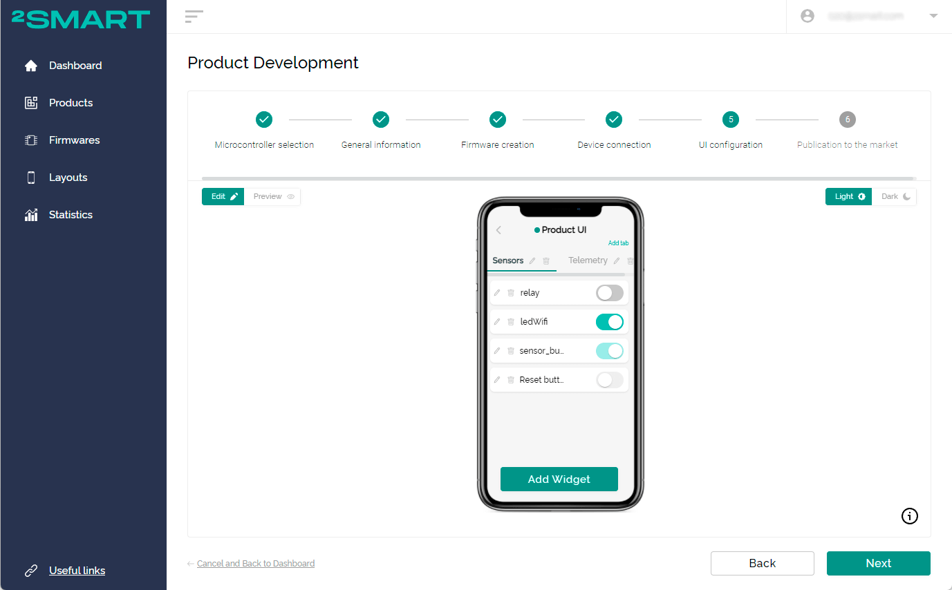
By default, widgets associated with all sensors on the device are added to the interface. To prevent end-users from having access to certain sensor data, you can simply remove the corresponding widgets in the app.
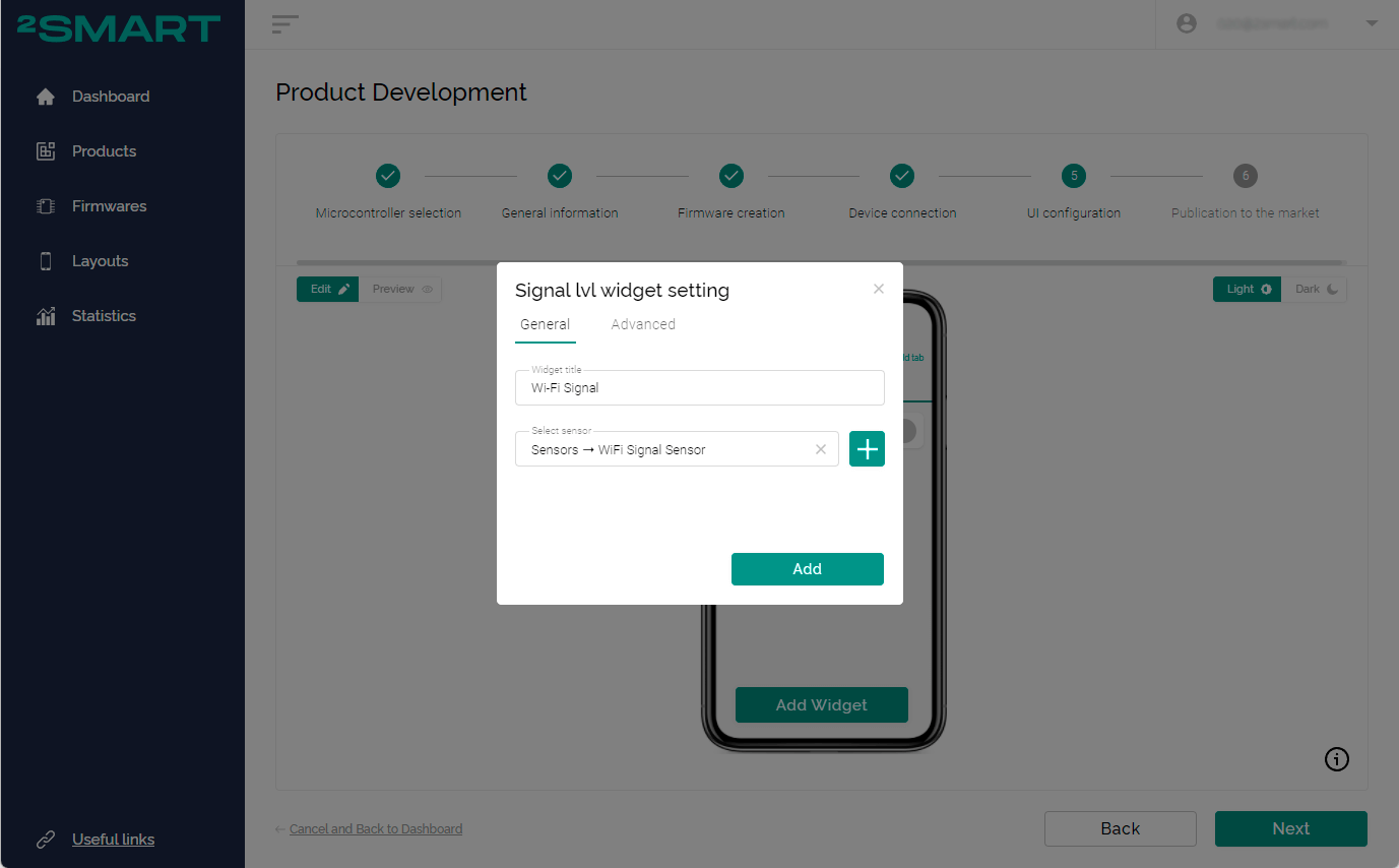
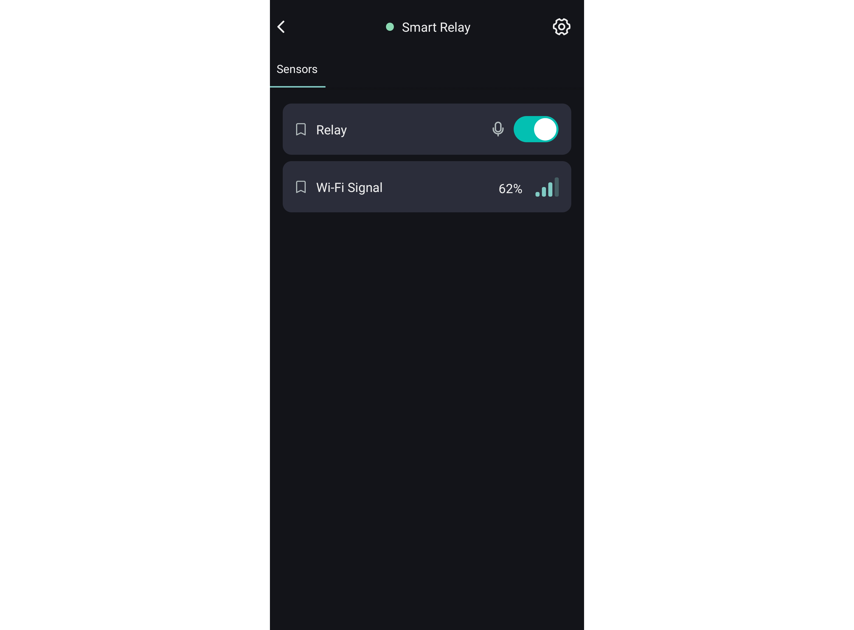
For the smart relay in our example, two widgets are enough: an on/off button for the relay, and a Wi-Fi signal strength sensor.
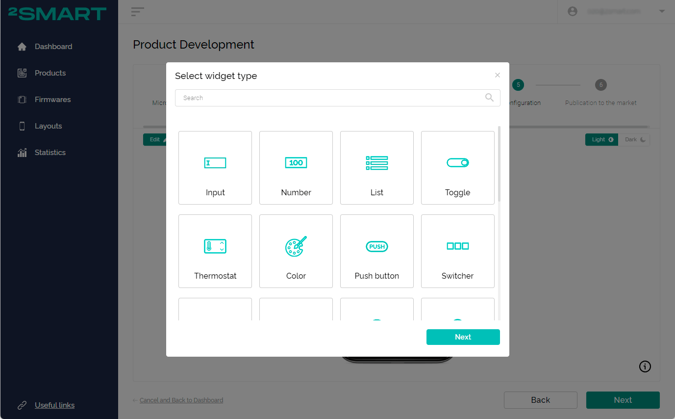
To change the order of the widgets in the list, use drag-and-drop. To add a new tab to the application, click the "Add Tab" link in the top right of the Emulator screen.
The library of widgets on the platform is quite diverse, and most of them are universal and suitable for different devices. The library is simple to grasp and you can safely choose any widget. In their respective settings, it will be clear with which sensors of your device it can be used.
2 - Use the preview mode to see the application interface without editing tools.
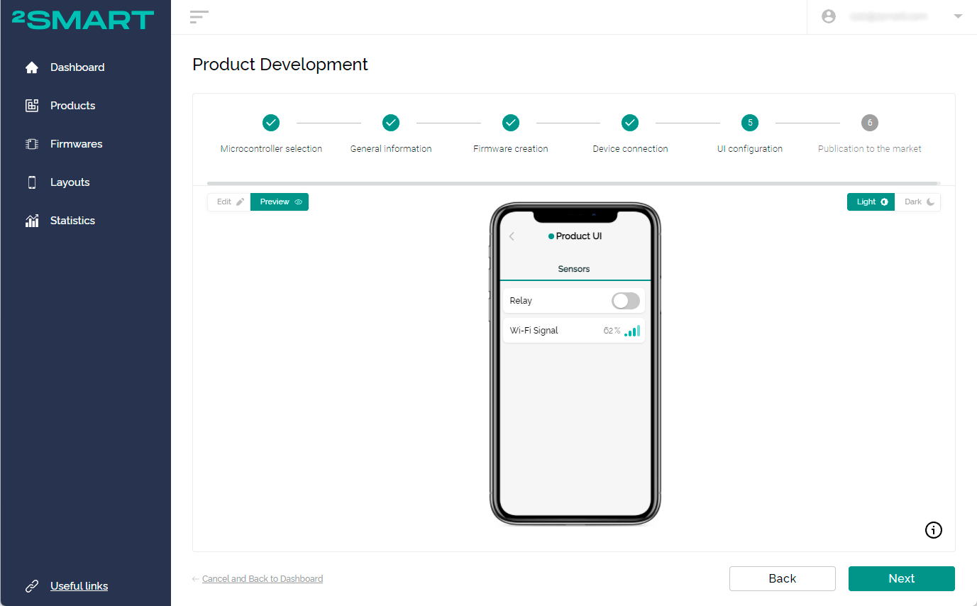
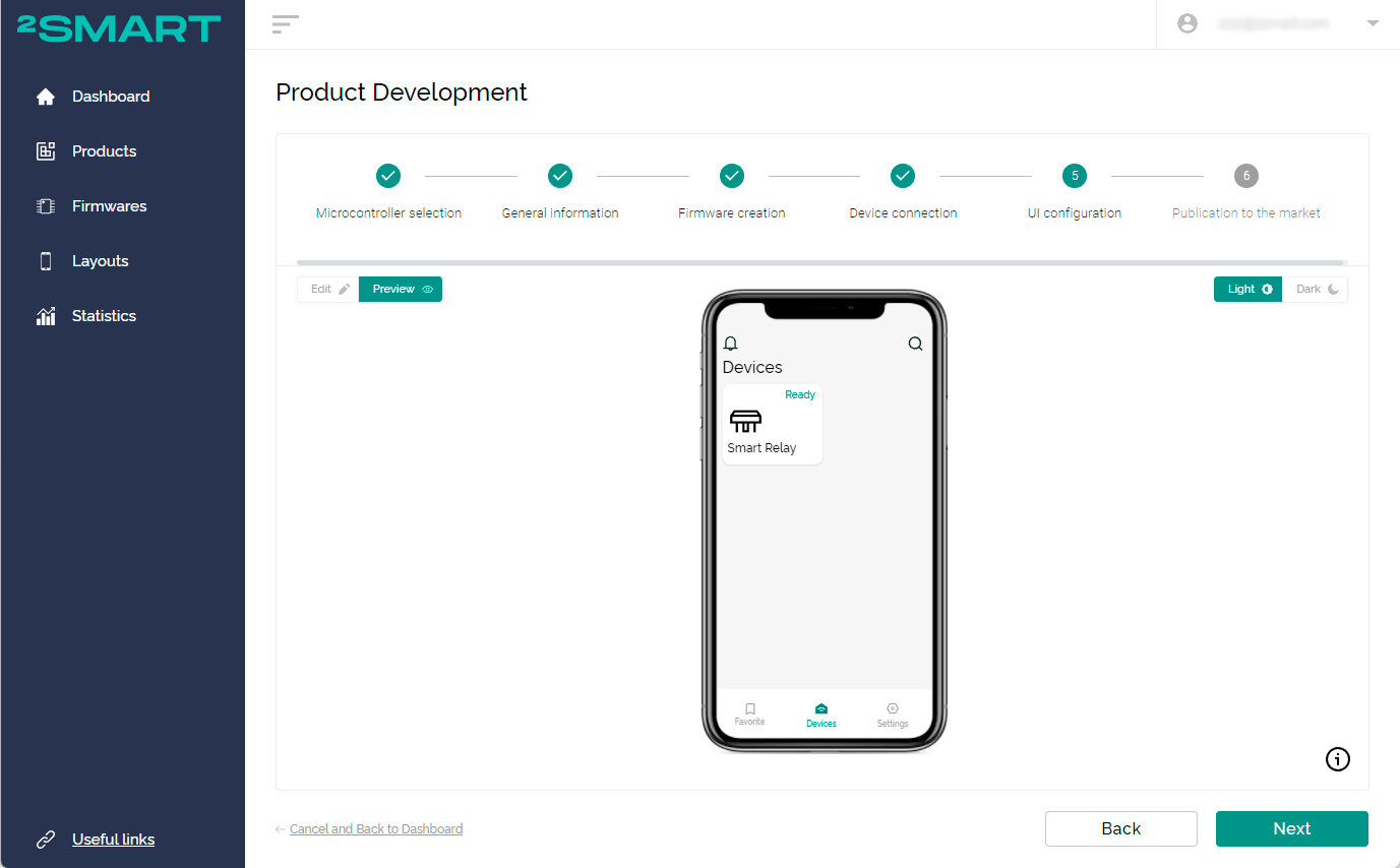
The device can be controlled during the process of editing the application interface. In the case of the smart relay built using our scheme, you can see that the green LED lights up when you turn on the “relay” widget. At the same moment, the lamp or any other device that is connected through the relay will start. When the relay is switched off, the red standby light on its housing will light up.
The device responds to switching off the relay widget on the emulator screen of the mobile application and vice-versa. Pressing the relay toggle button on the board in the interface of the mobile application, the emulator will instantly change the status of the widget.
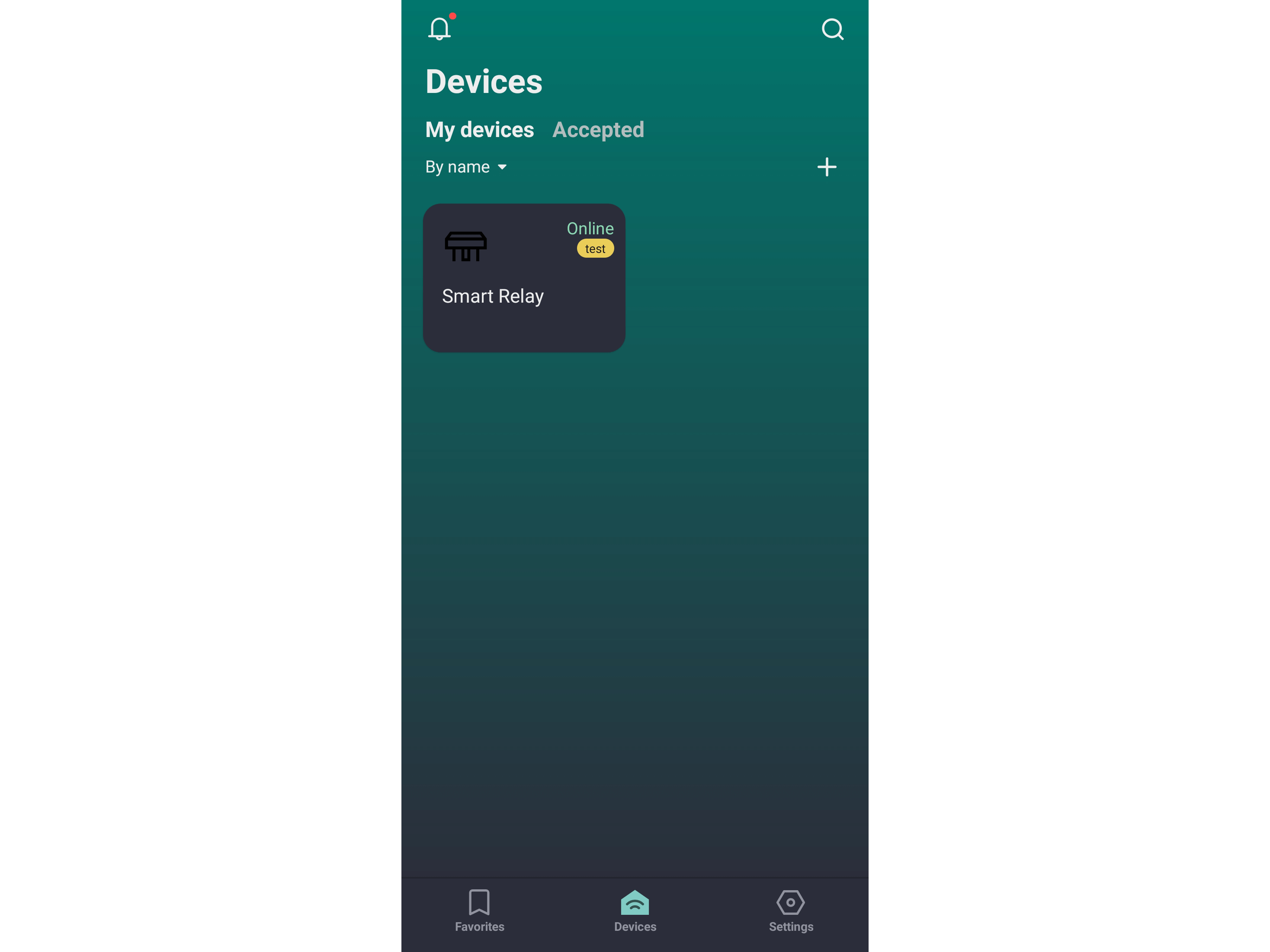
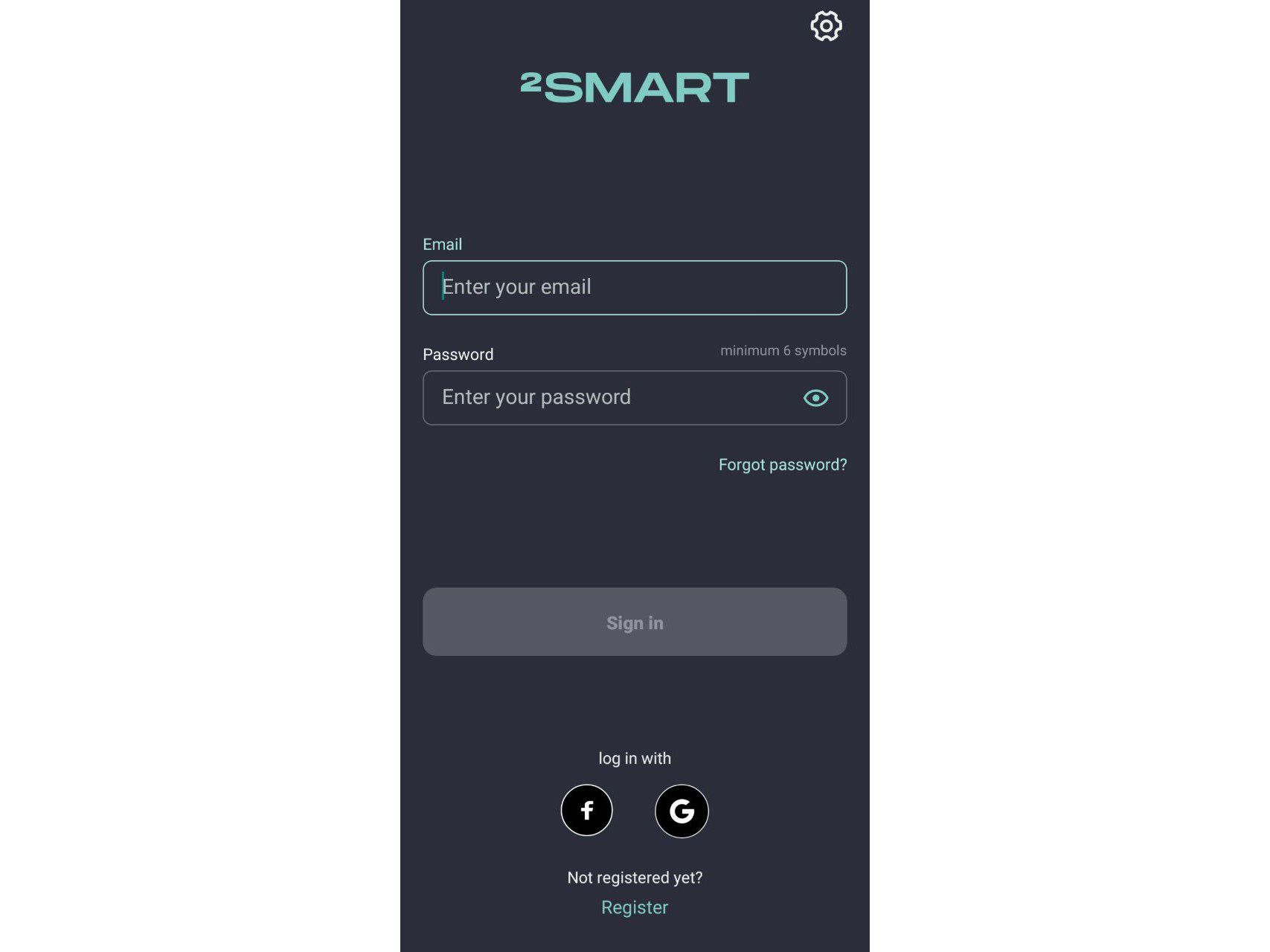
3 - After altering the mobile app interface settings, you can test it on your smartphone. Download the 2Smart Cloud app, install it on your phone and log in with the same credentials as on the platform.#nbsp;Your prototype is already on the Device screen marked "Test".
Note that users will manage the device solely from this application. For it to happen, you need to complete the product settings and publish the device in the 2Smart Cloud directory.
After logging into the application with the same parameters as you registered in the web panel, the newly created device will be available in the "Devices" tab. The device management interface in this case fully corresponds to the one that was configured in the application emulator.
Note that the device can be controlled from the mobile app, its emulator in the vendor panel, and by physical buttons on the device itself.#nbsp; Changes in the state of the sensors are instantly displayed in the interface of the application on the smartphone, as well as its emulator in the browser of the computer.
You can make changes to the application interface in the vendor panel. These include: editing the device’s name and icon, adding new widgets, and changing the order of existing widgets. All the changes will be visible after the application is restarted on the smartphone.
Building the production firmware and controlling the device from a smartphone
The firmware used previously is only for prototype testing. Its unfamiliarity is that the code contains technical data that is not necessary on the end-user’s device. These are parameters for connecting to the test environment and interacting with it.#nbsp;
The final production firmware is the version that is installed on devices that will go on sale. Its code no longer contains the additional parameters needed to test the prototype and the device is connected to the platform using a standard pairing method from the end-user’s account.
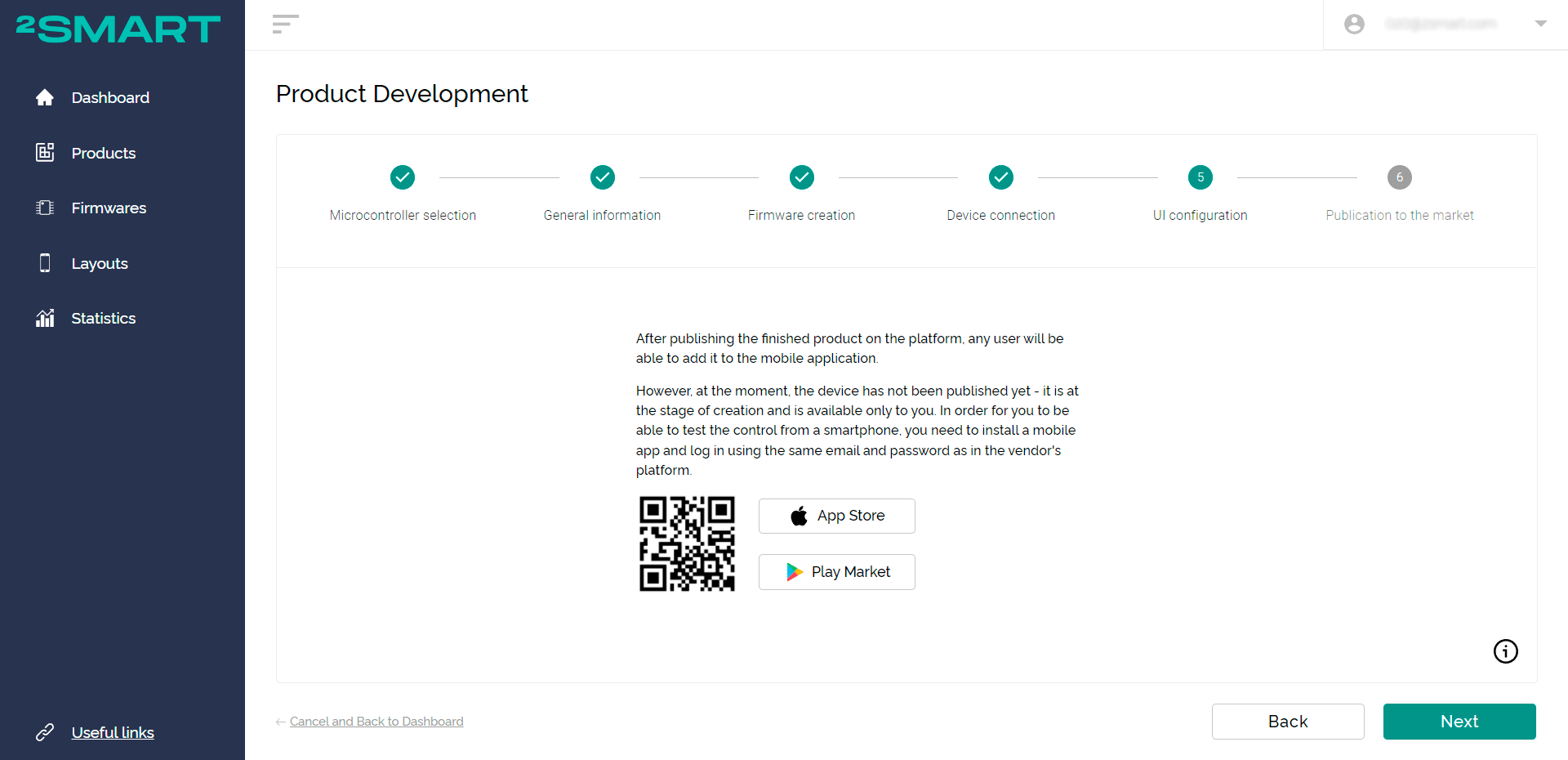
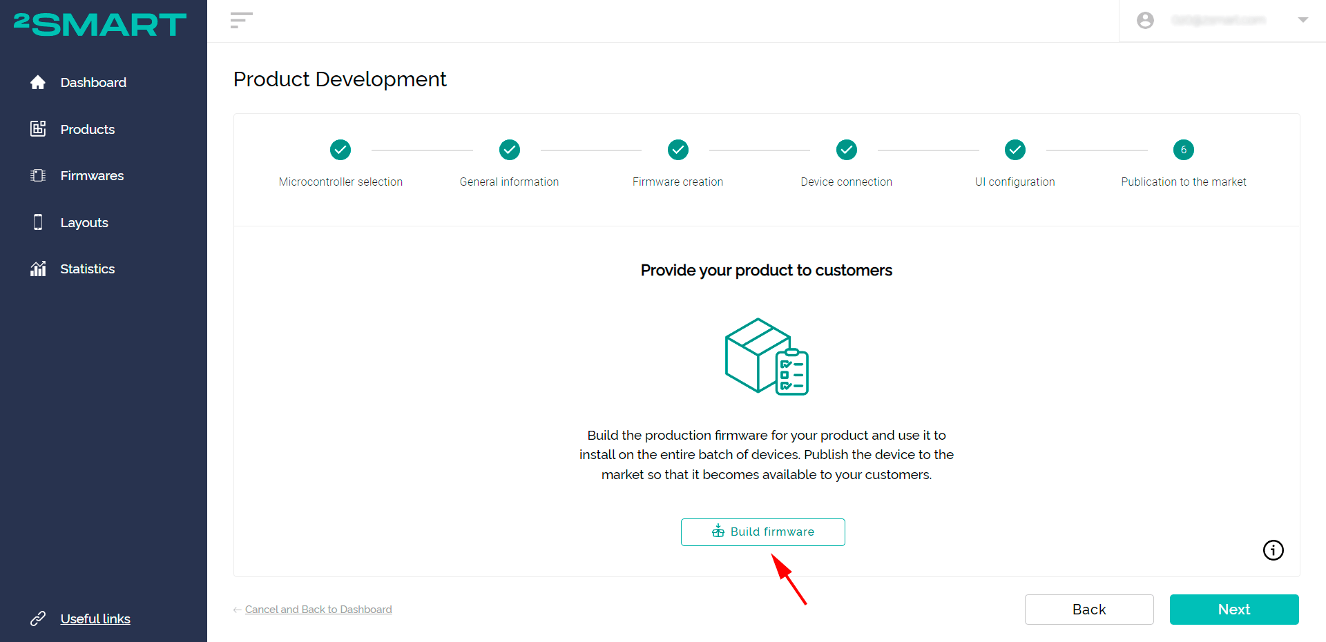
1 - Click "Next" in the window with the link to the mobile app. The production firmware build window opens. Click "Build firmware".
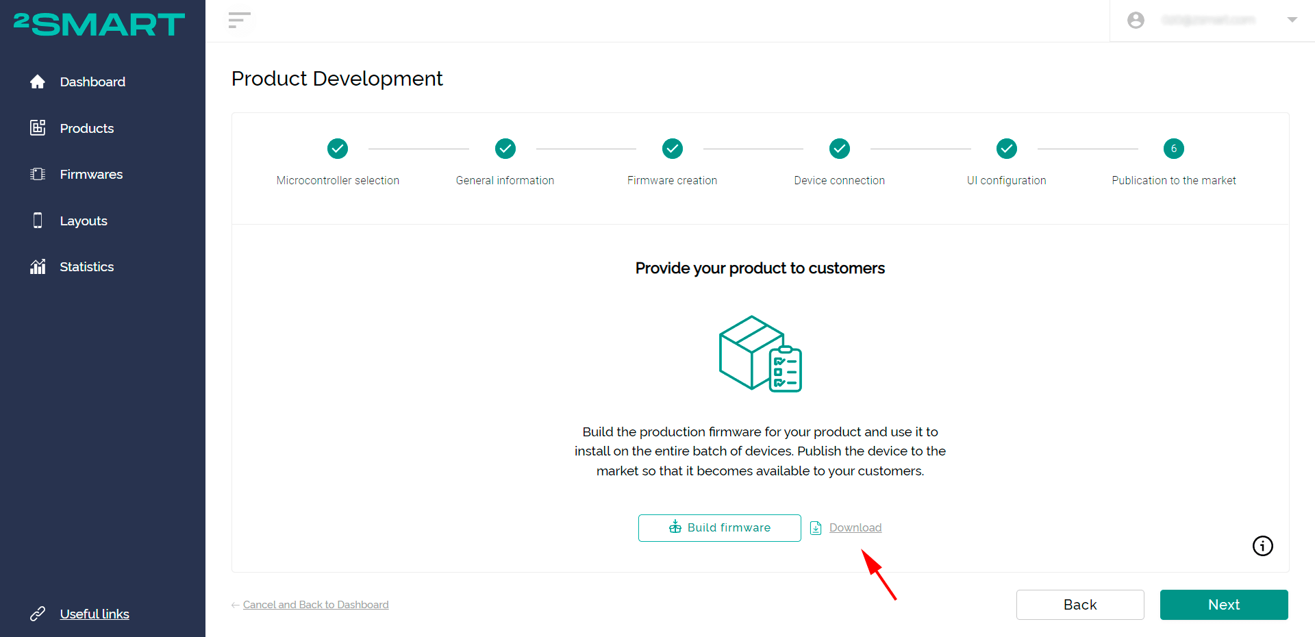
2 - Wait until the process is complete and click the "Download" link.
3 - Install the production version of the firmware on the device in the same way you installed the test version.
N.B. If the firmware is already added to the microcontroller, remove it as described in the ‘readme.md’ file or by following the documentation.
If you are interested in building another device, it is advised to install the final version of the firmware on the second device so the first one can be used as a prototype for testing and debugging the test firmware.
For a vendor who plans to release a batch of smart devices, this tip is all the more relevant.
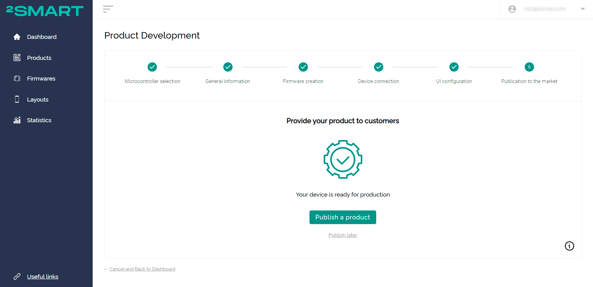
4 - Click "Next" on the production firmware build screen then select "Publish a product” on the publish product screen.
After publishing a product, you can add it to the 2Smart Cloud mobile app on your smartphone and start using the device. The published product can also be added to the mobile apps of the customers using your device.
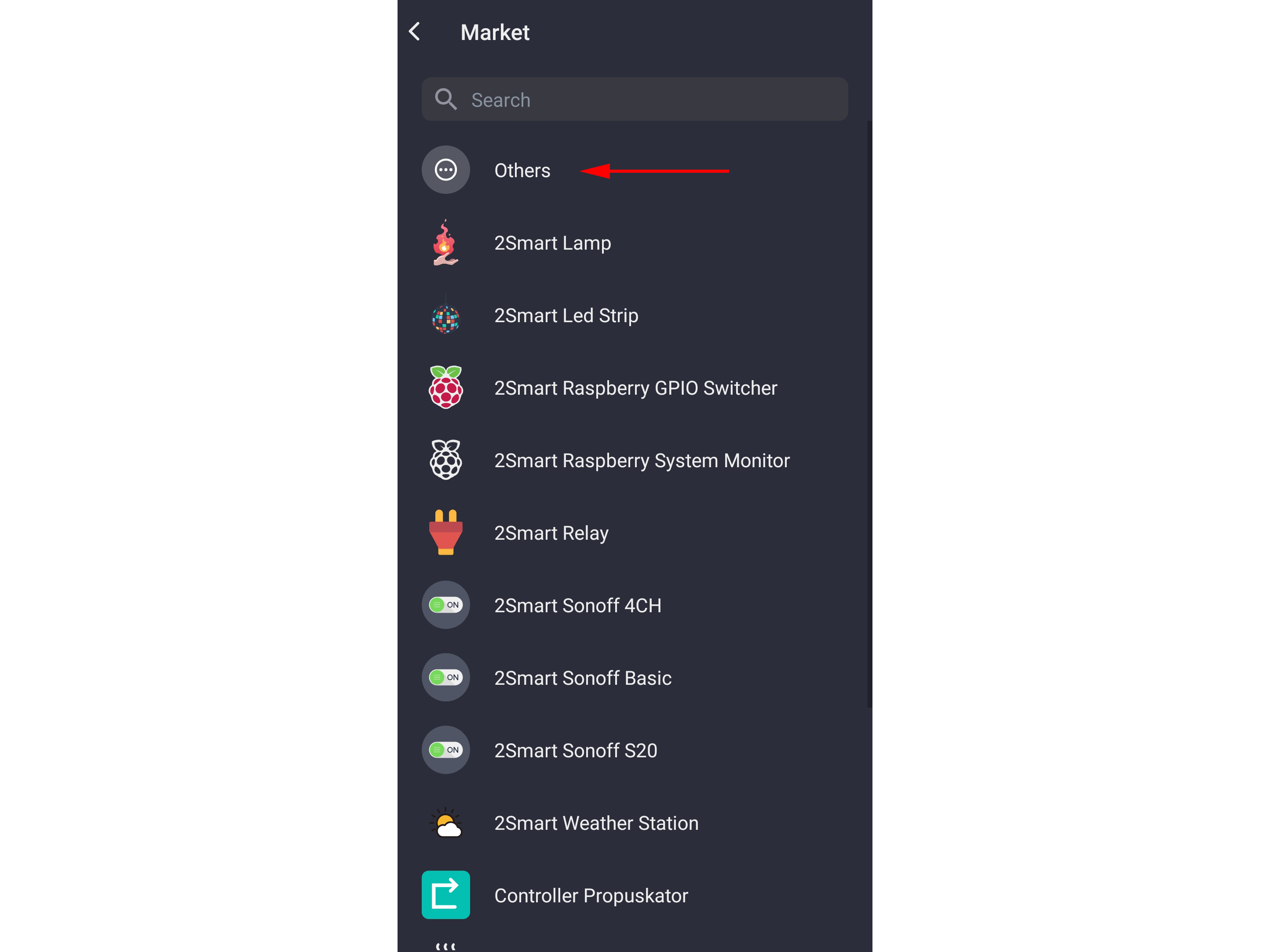
Do note that the product will only appear in the public catalog once it is approved by the platform administrators. Until then, your only option is to add the device through the pairing procedure by selecting "Others" in the market.
5 - When published, the product page opens in the vendor panel. It can be accessed through the "Products" menu and the status of the product should read "Published".

Pairing device to the 2Smart Cloud application
To truly put your product to the test, imagine you are the person buying the device. Add a device from the catalog using the recommended steps:
1 - Install the 2Smart Cloud app (iOS | Android).
2 - Create an account, or sign in with a Google or Facebook account.
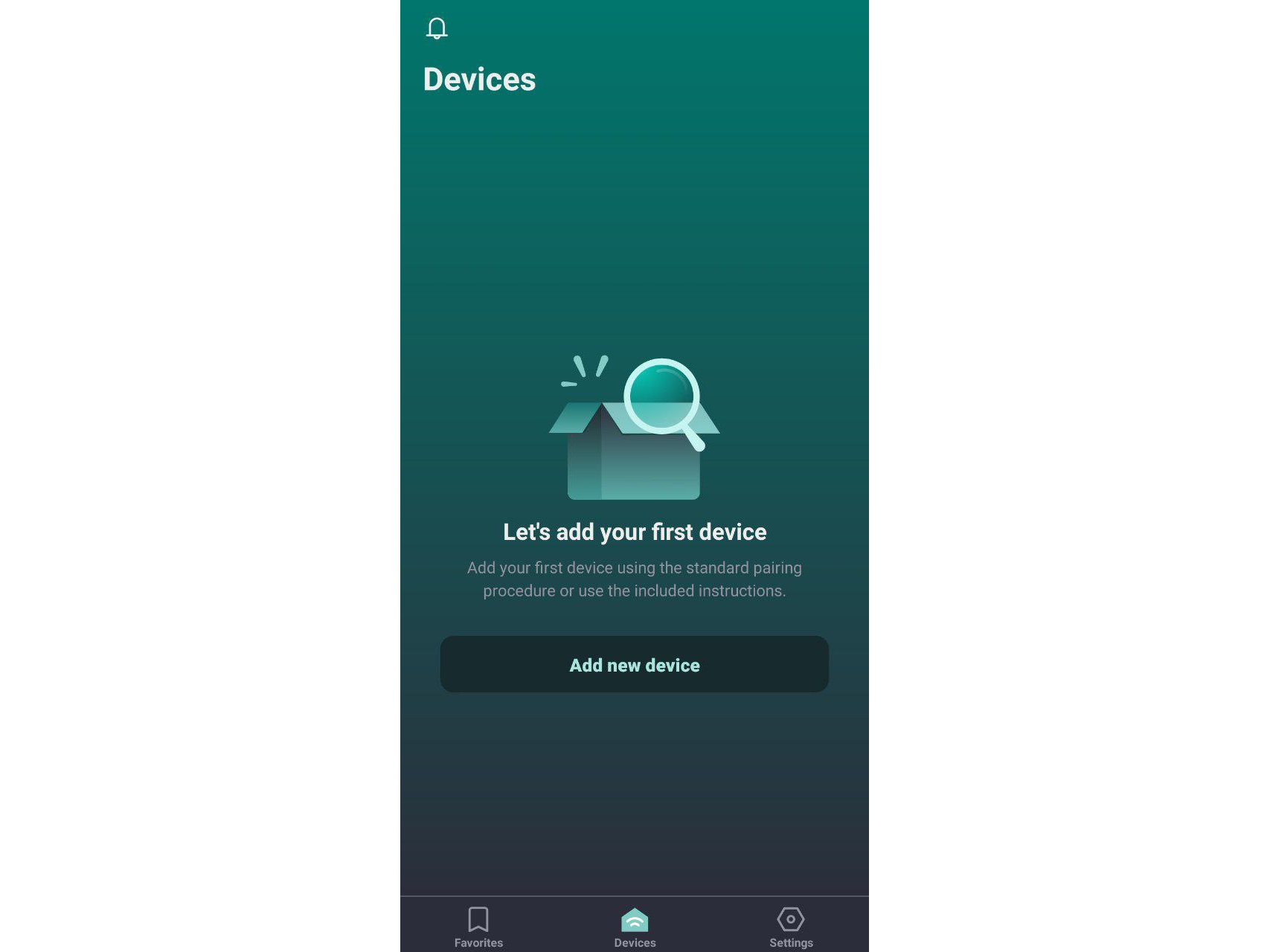
3 - Select the “Devices" tab and click "Add new device".
4 - Select your product from the list. It will appear under the name and icon you specified in the vendor panel. If the product is not yet approved by the platform administrators, look for#nbsp; “Others” and click “Continue”.
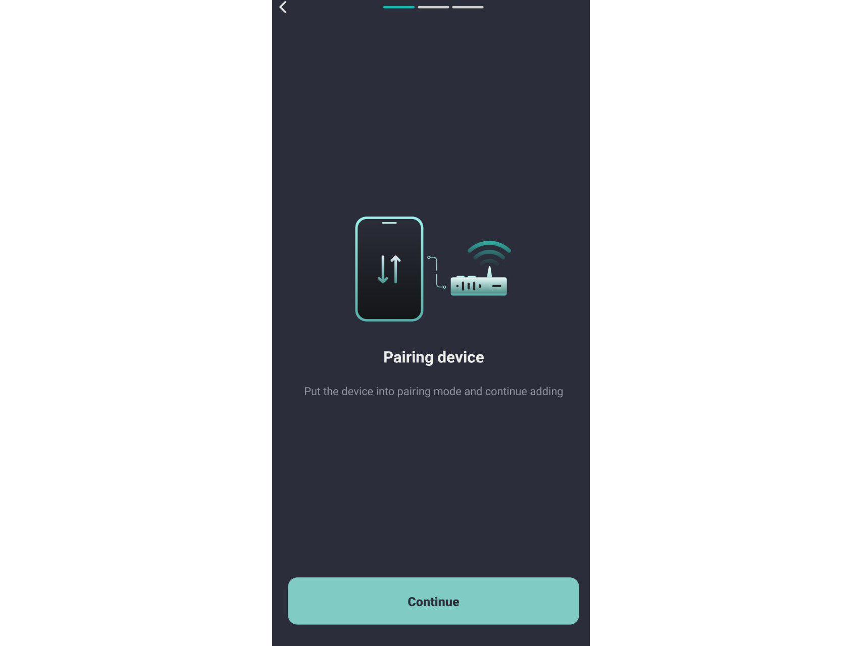
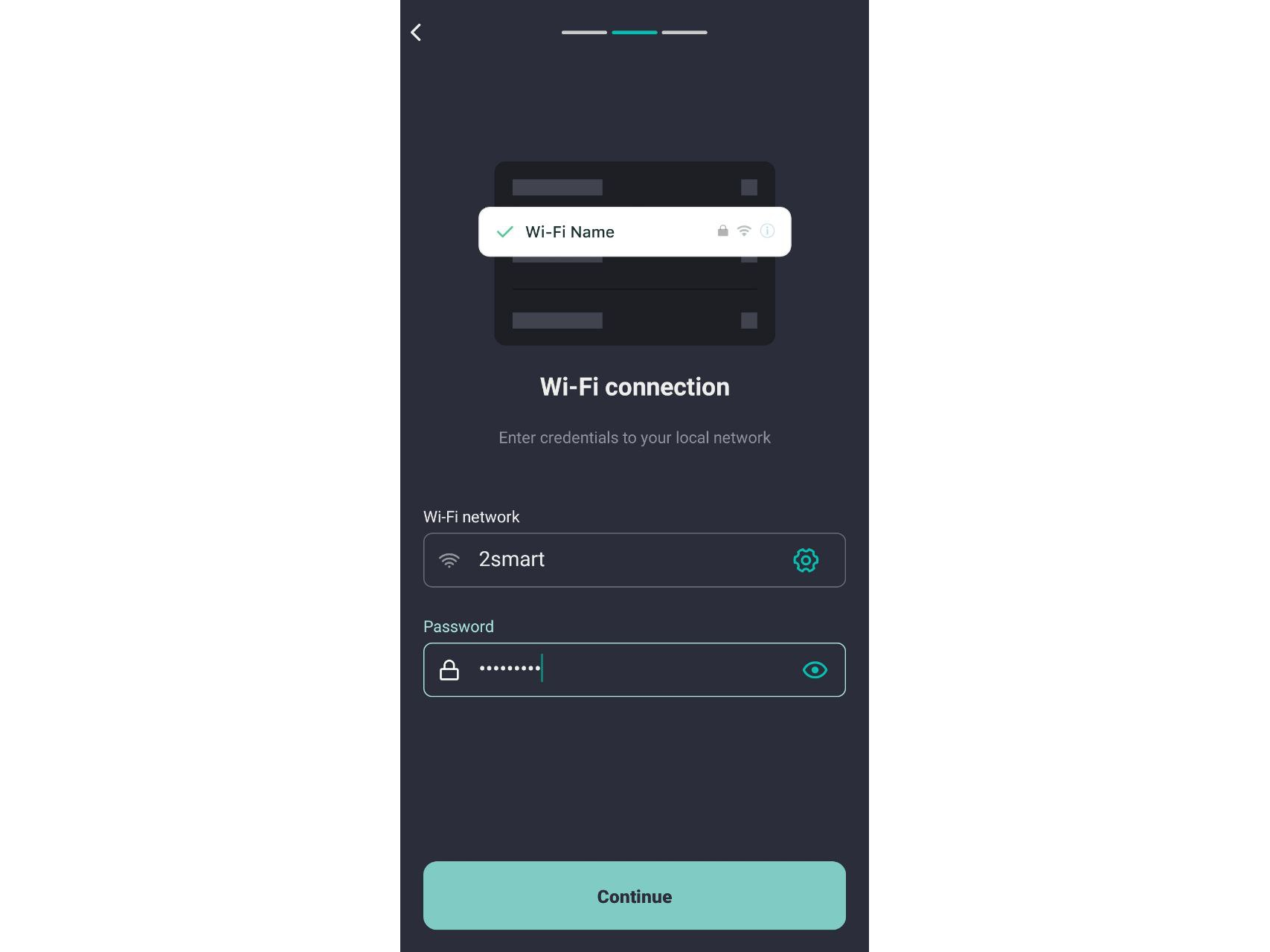
5 - Enter the details of the Wi-Fi network that your IoT device will use. Click "Continue".
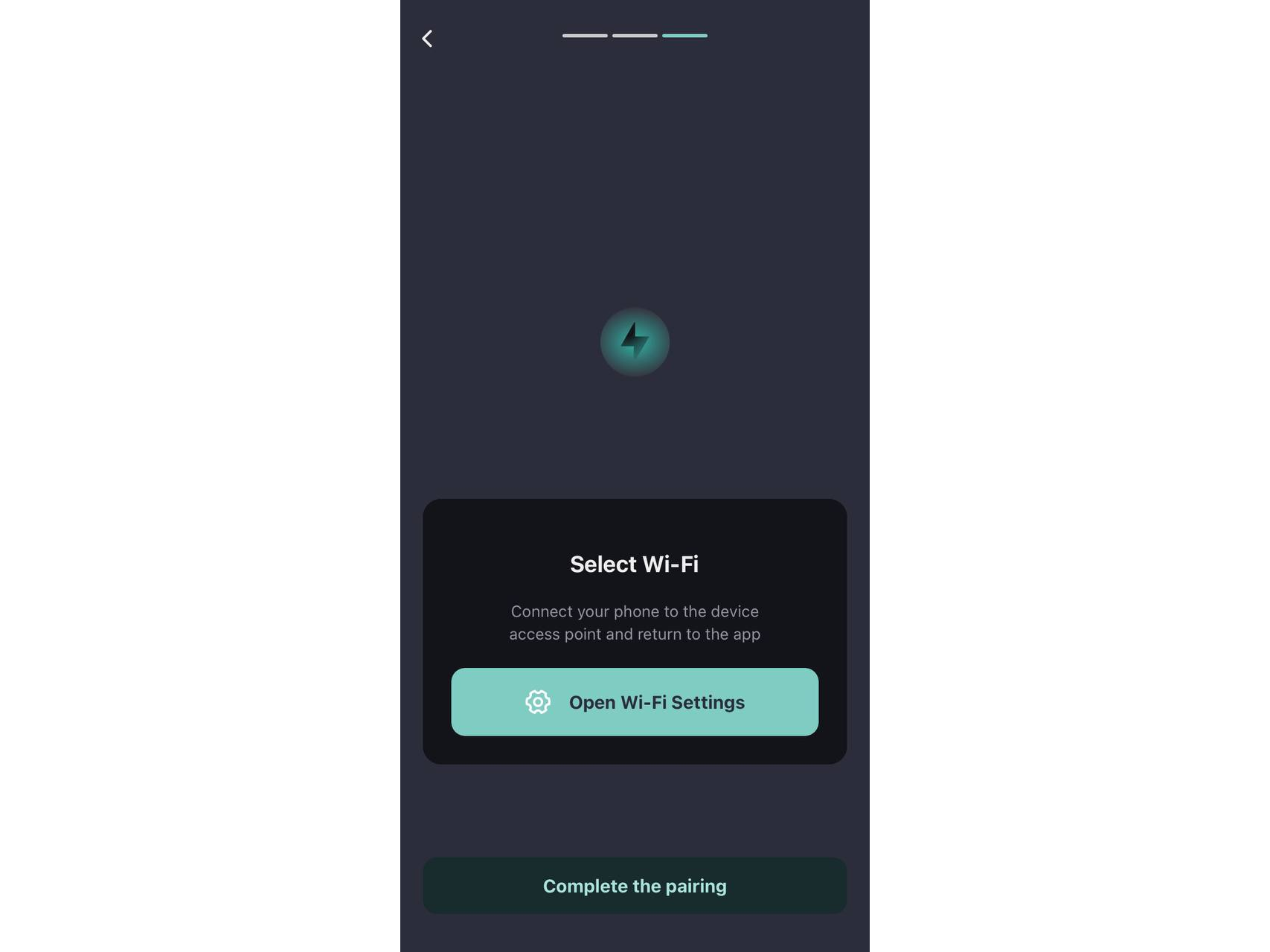
6 - Tap the "Open Wi-Fi Settings" link to connect your phone to the device's access point.
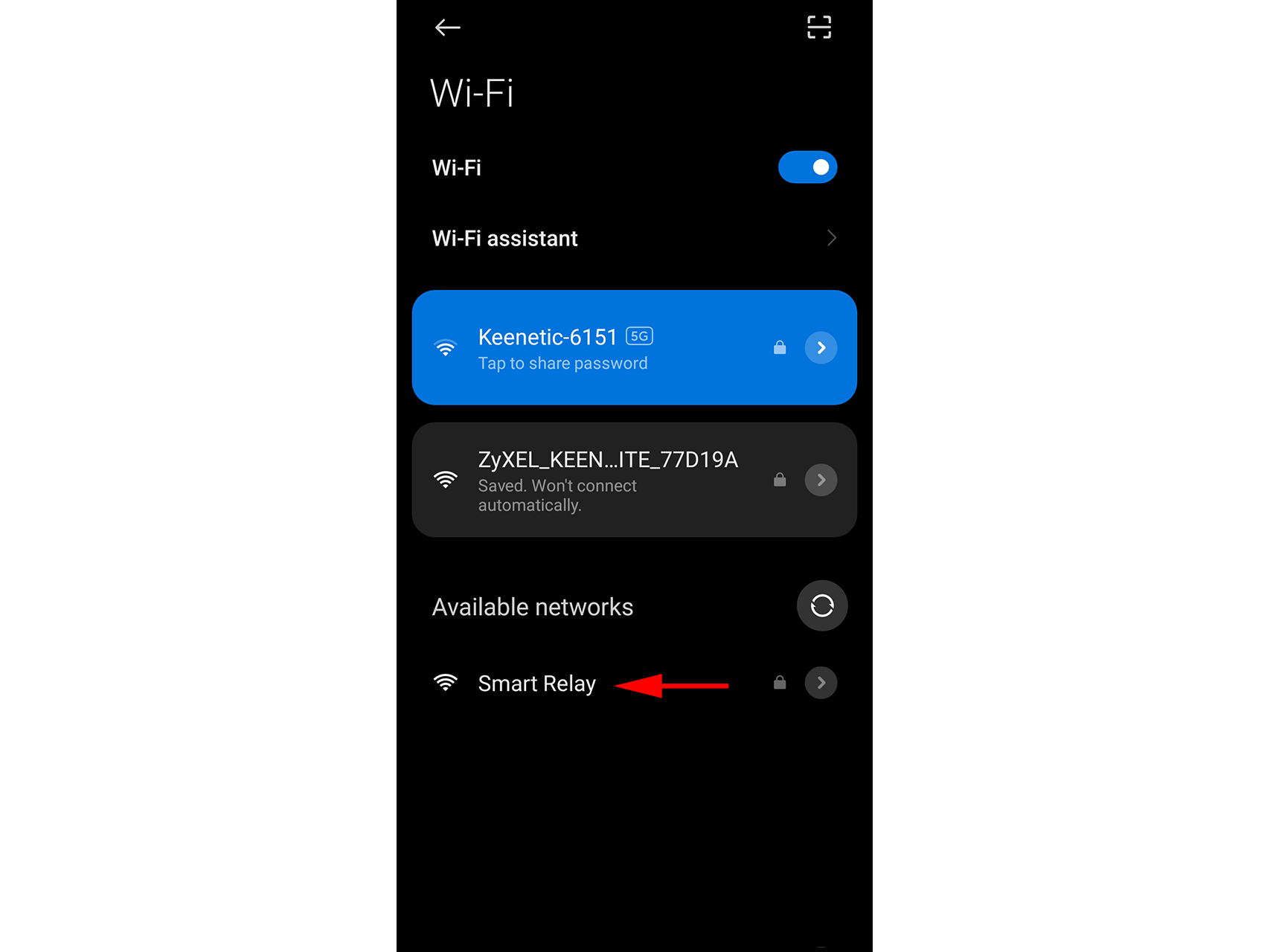
7 - In the list of available networks, find the network selected by your device. For ESP32-based products, the network name corresponds to the product name. The network should be open and not require a password. Connect to said network.
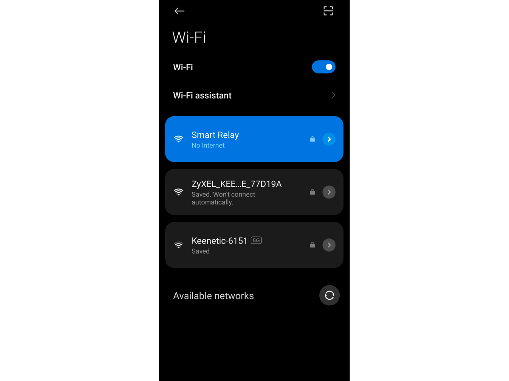
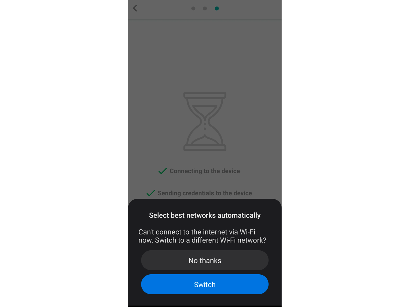
8 - In a case where your smartphone offers to switch to a network with Internet access, decline.
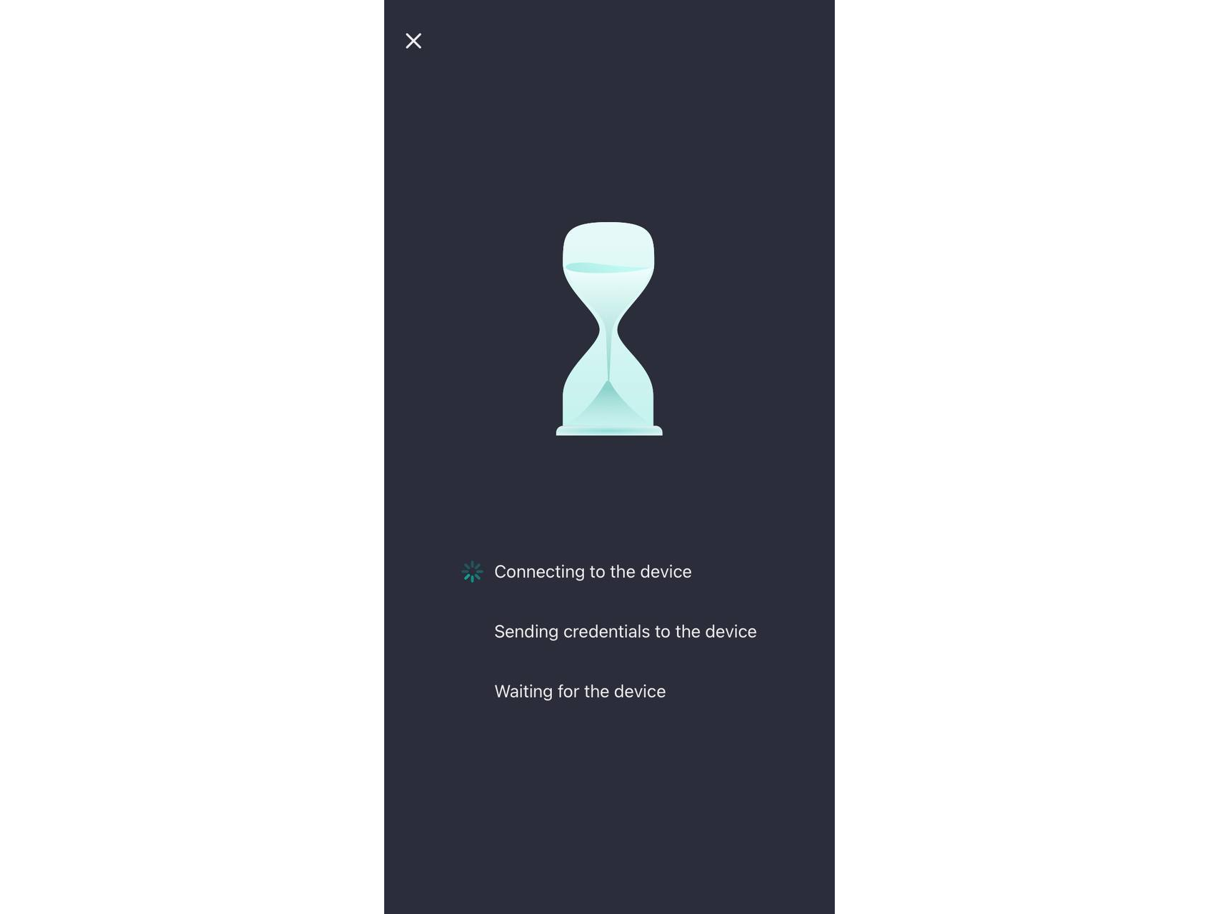
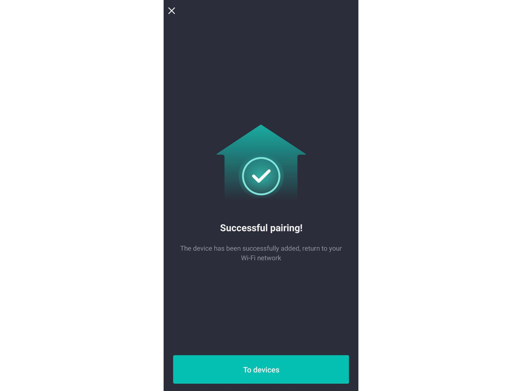
9 - Wait until the device is successfully added to the app.
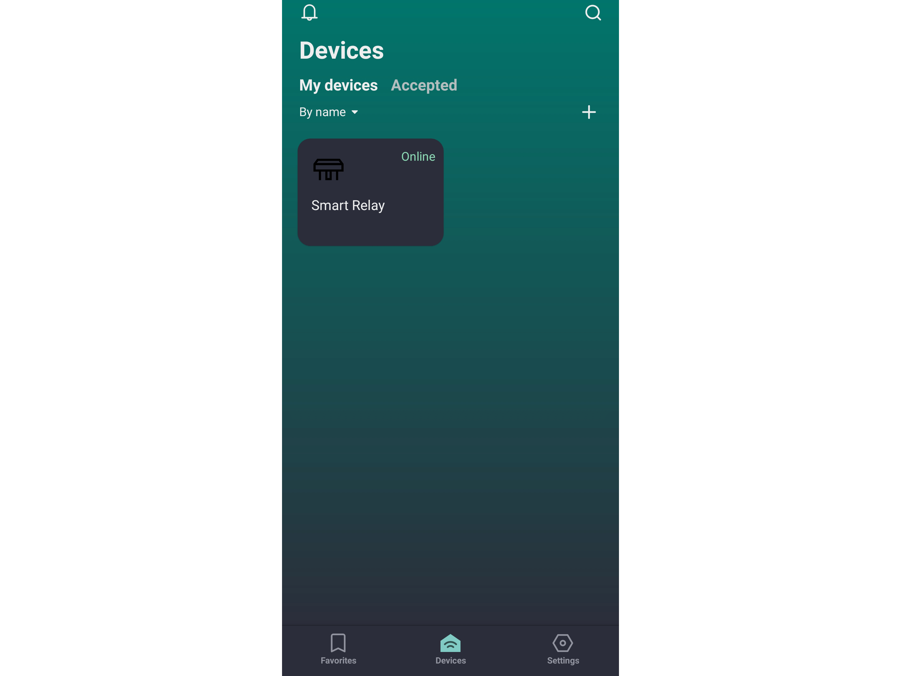
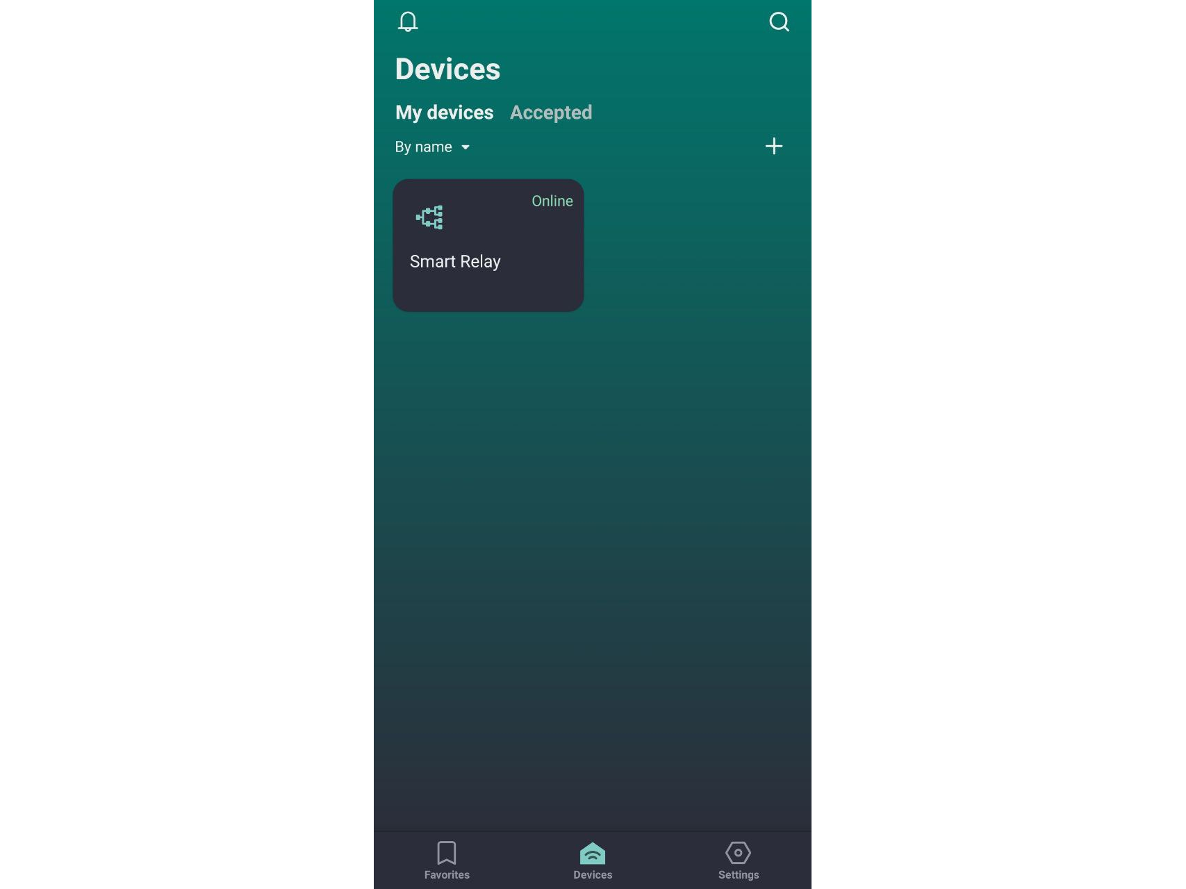
10 - Click the “Devices” tab and make sure the device appears in the list. Notice that the device name and icon match what you specified when creating the product.
11 - Click on the device icon and the control interface that has been configured in the vendor's cabinet will be visible. Make use of#nbsp; widgets to control the device. In our case, it is the relay switch installed in the vendor's panel and the Wi-Fi signal viewer widget.
12 - You can use additional device management features that the 2Smart Cloud app provides by default. For example, voice commands, a Telegram bot, and control via phone call. Detailed instructions can be found in the blog on our website.
13 - One can quickly share access to your device with your family and friends using the "Share" menu in the app settings. Detailed instructions are in the blog on our website.
There you have it! All that's left is to power an ordinary table lamp through a smart relay and make it respond to commands from the mobile app. Keep the safety precautions in mind when connecting the power.